Bar Bending Schedule for Footings | Steel Quantity of Footing | Estimation of Reinforcement in Footing | BBS of Rectangular Footing
In this Article today we will talk about the Bar Bending Schedule for Footings | Steel Quantity for Footings | Estimation of Reinforcement in Footing | BBS of Rectangular Footing | Steel Estimation for Footings | Footing Estimate Calculation
Bar Bending Schedule for footings:
Bar Bending Schedule plays a vital role in the construction of High rise buildings. It is very important to learn Bar Bending Schedule for finding out the quantities of Steel reinforcement required for every component of the building.
For Suppose, consider the case of high rise buildings, It requires tons of steel to complete 10+ floor building. It’s impossible to order all the steel required for whole construction at a time it creates a problem of space and also steel is prone to corrosion by the contact of water (rain). To avoid this, high rise building orders reinforcement (steel) as per requirement. Firstly they find the Estimation of Steel reinforcement in footings (steel quantities) [Bar Bending Schedule for footings], required for the construction of footings. After the completion of footings they go for next order and so on.
If you are new to Bar Bending Schedule, Refer the Basics of Bar Bending schedule
If you wanted to know different types of footings check here Different types of footings
Quantity of Reinforcement (Steel) required for footings / Bar Bending Schedule for footings:
The procedure to finding out the quantities of steel required for the footings, We are considering the below footing plan.
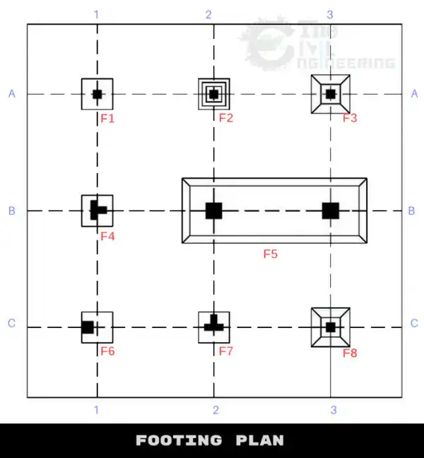 Observations from the above fig:
- F1, F4, F7 is Plain footing (1.0 × 1.0 × 0.8)
- F2 is Stepped Footing (0.9 × 0.9 × 1.35)
- F3, F8 is Isolated footing (0.9 × 0.9 × 0.5)
- F5 is Combined Isolated footing (4.2 × 1.7 × 0.9)
- F6 is Shoe footing (0.6 × 0.6 × 0.4)
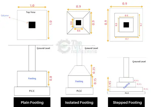
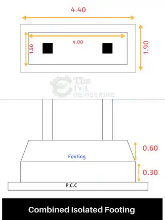 We use different types of mesh (reinforcement) in footings as per design. Steel Quantity for Footings
OTHER POSTS:
-
Spread Footing or Isolated Footing Reinforcement Detail
-
What is Concrete Cover | Concrete Cover for Slab, Beam, Column, Footing
-
Useful Tips for Design of RCC Members | Beam, Column, Slab, Footing
Steps involved in calculating the bar bending schedule of a footings:
Remember, Steel required for construction is ordered in Kgs or Number of Bars. The standard size of each bar is 12m. The final output of BBS calculation is in Kgs or in Number of “12m” Bars.- Deduct the concrete cover to find the dimensions of bars.
- Find the Length of single X Bars & Y Bars
- Find the total length of X bars. & Y bars
- Calculate the weight of steel required per 1m
- Calculate the total number of 12m bars required
- Find the total weight of steel required.
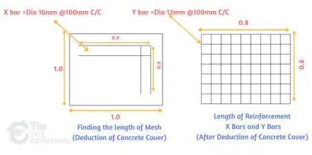
Plain footing Bar Bending schedule | F1, F4, F7
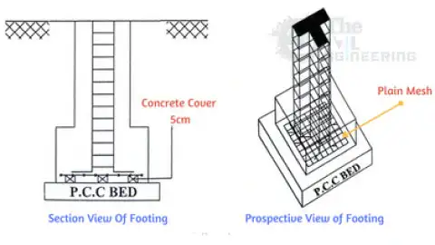
- Dimensions of Footing are 1.0 × 1.0 × 0.9 (Length × Breadth × Depth)
- Plain mesh is adopted for F1, F4, F7 footings
- Dia of X Bars is 16mm (Dia 16mm @ 100mm C/C)
- Dia of Y Bars is 12mm (Dia 12mm @ 100mm C/C)
- which means Center to center spacing between X bars & Y bars is 100mm
| Length of
Each X bar |
= 0.8m |
| Length of
Each Y bar |
= 0.8m |
| No. of X bars | [(Y Bar Length)/Spacing]+1
= [0.8/0.1]+1 = 9bars |
| No. of Y bars | [(X Bar Length)/Spacing]+1
= [0.8/0.1]+1 = 9bars |
| Total Length
of X bars |
= Length of each X bar ×
No. of X Bars = 0.8 × 9 =7.2m |
| Total Length
of Y bars |
= Length of each Y bar ×
No. of Y Bars = 0.8 × 9 =7.2m |
| Total No. of ’12m’
X bars |
= 7.2/12
= 0.6bars |
| Total No. of ’12m’
Y bars |
= 7.2/12
= 0.6bars |
| Weight of steel
required for 1m of 16mm bar |
= D2/162
= 162/162 = 1.58kg/m |
| Total weight of
steel required for X bars |
= 1.58 × 7.2
= 11.37Kgs |
| Weight of steel
required for 1m of 12mm bar |
= D2/162
= 122/162 = 0.88kg/m |
| Total weight of
steel required for Y bars |
= 0.88 × 7.2
= 6.33Kgs |
Isolated footings Bar Bending Schedule | F3, F8
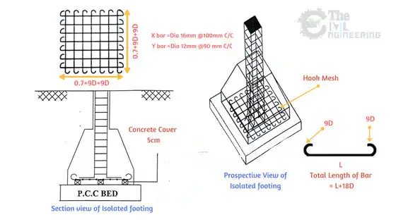
- Hook mesh is adopted for F3, F8 footings
- Dimensions of Footing are 0.9×0.9×0.5 (Length × Breadth × Depth)
- Dia of X Bars is 16mm (Dia 16mm @ 100mm C/C)
- Dia of Y Bars is 12mm (Dia 12mm @ 90mm C/C)
- which means Center to center spacing between X bars is 100mm & Y bars is 90mm
| Length of
Each X bar |
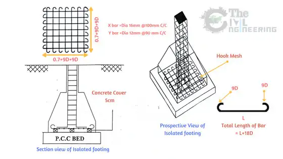
= 0.7+2×9d
d = 16mm = 0.016m = 0.7+2×9×0.016 = 0.988m |
| Length of
Each Y bar |
= 0.7+2×9d
d = 12mm = 0.012m = 0.7+2×9×0.012 = 0.916m |
| No. of X bars | [(Y Bar Length)/Spacing]+1
= [0.7/0.1]+1 = 8bars (Don’t include hook length in calculating no. of bars) |
| No. of Y bars | [(X Bar Length)/Spacing]+1
= [0.7/0.09]+1 = 9bars |
| Total Length
of X bars |
= Length of each X bar ×
No. of X Bars = 0.988 × 8 =7.9m |
| Total Length
of Y bars |
= Length of each Y bar ×
No. of Y Bars = 0.916 × 9 =8.24m |
| Total No. of ’12m’
X bars |
= 7.9/12
= 0.65bars |
| Total No. of ’12m’
Y bars |
= 8.24/12
= 0.68bars |
| Weight of steel
required for 1m of 16mm bar |
= D2/162
= 162/162 = 1.58kg/m |
| Total weight of
steel required for X bars |
= 1.58 × 7.9
= 12.48Kgs |
| Weight of steel
required for 1m of 12mm bar |
= D2/162
= 122/162 = 0.88kg/m |
| Total weight of
steel required for Y bars |
= 0.88 × 8.24
= 7.25Kgs |
Stepped footings Bar Bending Schedule | F2
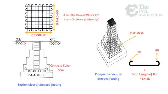
- Hook mesh is adopted for F2 footings
- Dimensions of Footing are 0.9 × 0.9 × 1.35 (Length × Breadth × Depth)
- Dia of X Bars is 16mm (Dia 16mm@110mm C/C)
- Dia of Y Bars is 20mm (Dia 12mm@115mm C/C)
- which means Center to center spacing between X bars is 110mm & Y bars is 115mm
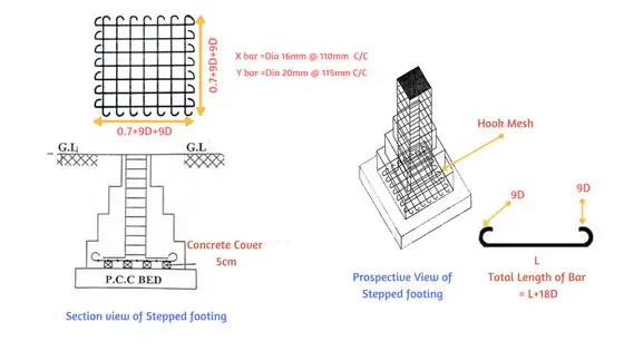
| Length of
Each X bar |
= 0.7+2×9d
d = 16mm = 0.016m = 0.7+2×9×0.016 = 0.988m |
| Length of
Each Y bar |
= 0.7+2×9d
d = 12mm = 0.012m = 0.7+2×9×0.020 = 1.06m |
| No. of X bars | [(Y Bar Length)/Spacing]+1
= [0.7/0.11]+1 =~7bars (Don’t include hook length in calculating no. of bars) |
| No. of Y bars | [(X Bar Length)/Spacing]+1
= [0.7/0.115]+1 = ~6bars |
| Total Length
of X bars |
= Length of each X bar ×
No. of X Bars = 0.988 × 7 =7.9m |
| Total Length
of Y bars |
= Length of each Y bar ×
No. of Y Bars = 1.06 × 6 =6.36m |
| Total No. of ’12m’
X bars |
= 7.9/12
= 0.65bars |
| Total No. of ’12m’
Y bars |
= 6.36/12
= 0.53bars |
| Weight of steel
required for 1m of 16mm bar |
= D2/162
= 162/162 = 1.58kg/m |
| Total weight of
steel required for X bars |
= 1.58 × 7.9
= 12.48Kgs |
| Weight of steel
required for 1m of 12mm bar |
= D2/162
= 202/162 = 2.46kg/m |
| Total weight of
steel required for Y bars |
= 2.46 × 6.36
= 15.64Kgs |
Eccentric/Shoe footings Bar Bending Schedule | F6
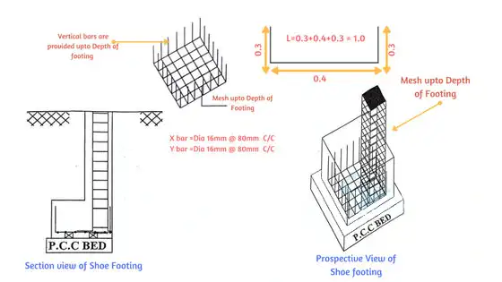
- Mesh extended till Depth of Footing is adopted for F6 footings
- Dimensions of Footing are 0.6 × 0.6 × 0.4 (Length × Breadth × Depth)
- Dia of X Bars is 16mm (Dia 16mm@80mm C/C)
- Dia of Y Bars is 16mm (Dia 16mm@80mm C/C)
- which means Center to center spacing between X bars & Y bars is 80mm
| Length of
Each X bar |
= 0.4+0.3+0.3
= 1.0m |
| Length of
Each Y bar |
= 0.4+0.3+0.3
= 1.0m |
| No. of X bars | [(Y Bar Length)/Spacing]+1
= [0.4/0.08]+1 =~6bars (Don’t include extra bar length in calculating no. of bars) |
| No. of Y bars | [(X Bar Length)/Spacing]+1
= [0.4/0.08]+1 = ~6bars |
| Total Length
of X bars |
= Length of each X bar ×
No. of X Bars = 1.0 × 6 =6m |
| Total Length
of Y bars |
= Length of each Y bar ×
No. of Y Bars = 1.0 × 6 =6m |
| Total No. of ’12m’
X bars |
= 6/12
= 0.5bars |
| Total No. of ’12m’
Y bars |
= 6./12
= 0.5bars |
| Weight of steel
required for 1m of 16mm bar |
= D2/162
= 162/162 = 1.58kg/m |
| Total weight of
steel required for X bars |
= 1.58 × 6
= 9.48Kgs |
| Weight of steel
required for 1m of 12mm bar |
= D2/162
= 122/162 = 1.58kg/m |
| Total weight of
steel required for Y bars |
= 1.58 × 6
= 9.48Kgs |
Combined Footing Bar Bending Schedule | F5
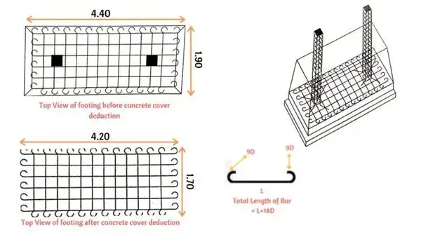
For the calculation of the total quantity of steel required for the combined footing, we are adopting these dimensions for bars. Steel Estimation for Footings
- Hook Mesh is usually adopted for F5 footing.
- Dimensions of Footing are 4.2 × 1.7 × 0.9 (Length × Breadth × Depth)
- Dia of X Bars is 12mm (Dia 12mm@100mm C/C)
- Dia of Y Bars is 12mm (Dia 12mm@100mm C/C)
- which means Center to center spacing between X bars & Y bars is 100mm
| Length of
Each X bar |
= 4.2+2×9d
d = 12mm = 0.012m = 4+2×9×0.012 = 4.41m |
| Length of
Each Y bar |
= 1.7+2×9d
d = 12mm = 0.012m = 1.7+2×9×0.012 = 1.91m |
| No. of X bars | [(Y Bar Length)/Spacing]+1
= [1.7/0.1]+1 =18bars (Don’t include hook length in calculating no. of bars) |
| No. of Y bars | [(X Bar Length)/Spacing]+1
= [4.2/0.1]+1 = 43bars |
| Total Length
of X bars |
= Length of each X bar ×
No. of X Bars = 4.41 × 18 =79.38m |
| Total Length
of Y bars |
= Length of each Y bar ×
No. of Y Bars = 1.91 × 43 =82.13m |
| Total No. of ’12m’
X bars |
= 79.38/12
= 6.6bars |
| Total No. of ’12m’
Y bars |
= 82.13/12
= 6.84bars |
| Weight of steel
required for 1m of 16mm bar |
=D2/162
=122/162 =0.88kg/m |
| Total weight of
steel required for X bars |
= 0.88 × 79.38
= 69.85Kgs |
| Weight of steel
required for 1m of 12mm bar |
=D2/162
=122/162 =0.88kg/m |
| Total weight of
steel required for Y bars |
= 0.88 ×82.13
= 72.27Kgs |
Abstract of above calculation:


