How to Load Transfer from Slab to Beam – Formulas with Example
In this Article today we will talk about the Load Transfer from Slab to Beam | Structural Load Calculation | Load Calculation for Beam | Load Calculation of Building | Load Distribution form Slab to Beam | Structural Design Calculations | One Way Slab Load Distribution on Beam | Two Way Slab Load Distribution on Beam | Beam Load Calculation
Load Transfer from Slab to Beam?
In the design of reinforced concrete structures, floor loads are usually transferred from slabs to beams, and from the beams, the loads are transferred to the columns. Ultimately, the columns transfer the superstructure load to the foundation supporting the structure. Load transfer from slab to beams is one of the most intriguing aspects of reinforced concrete design, especially for beginners.
Usually, slab pressure loads (force per unit area) are transferred to the supporting beams as line loads (force per unit length). The line load can be triangular, trapezoidal, or partially distributed on the beam. Depending on the analytical method employed in the design, some idealisations can be made in order to simulate load transfer from slab to beam. The most popular methods of transferring slab load to beams are; Structural Load Calculation
- Finite element analysis
- Yield line method
- Approximate method using formula Load Calculation of Building
Finite element analysis is suited more to computer calculation since it can be a very lengthy process when done by hand. In this method, the slab is divided into finite element meshes connected by nodes. The reactive forces on each node along the beam are transferred to the beams (which must be broken into finite elements too with nodes connected to the slab).
In the yield line method, the most appropriate yield lines are constructed (usually at 45° angles) on the slab, and the corresponding load on each part of the yield line transferred to the beam adjacent to it. For two-way slabs, this method usually leads to trapezoidal and triangular loads on the beams..
In the manual design of structures, some formulas can be used to idealise slab loads on beams as uniformly distributed loads. The main reason for this is to simplify manual analysis since it is not a very accurate method. The results obtained from the method are usually very conservative.
Some of the formulas can be obtained from Reynolds and Steedman (2005) for transfer of load from two-way slab to beams. The formulas are presented below; Load Calculation of Building
- Two-way slab (ly/lx < 2)
- Long span: p = nlx/2(1 — 1/3k2)
- Short span: p = nlx/3
- One-way slab (ly/lx > 2)
- Long span: p = nlx/2
- Short span: p = nlx/5
Where;
n = load from slab
ly = length of long side of the slab
lx = length of short side pf the slab
k = aspect ratio = ly/lx
In this article, we are going to review load transfer from slab to beams using the three approaches;
- Full finite element analysis of beams and slabs using Staad Pro
- Yield line method of load transfer using Staad Pro
- Manual method using formula Load Calculation of Building
Two Way Slab Load Distribution on Beam:
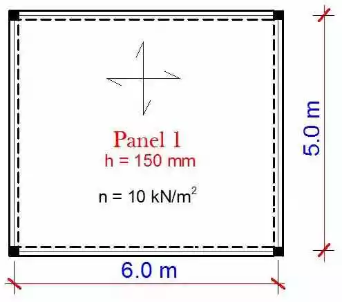
CASE 1: Two way slab of dimensions (5m x 6m) simply supported by beams on all sides and subjected to a pressure load of 10 kN/m2
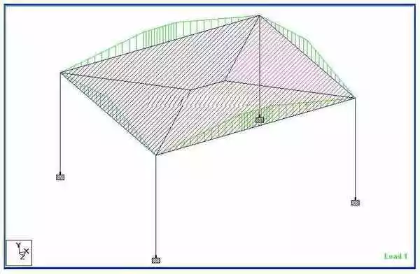
(a) Finite Element Analysis
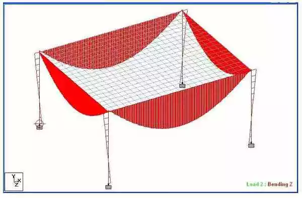
Maximum span moment = 73.063 kNm
Support moment = -2.71 kNm
End shear = 37.6 kN Load Distribution form Slab to Beam
Maximum span moment = 54.495 kNm
Support moment =4814 kNm
End shear = 31.9 kN Load Distribution form Slab to Beam
(b) Yield line method
![]()
Long span beam:
Maximum span moment = 76.562 kNm
Support moment = -9.897 kNm
End shear = 39.4 kN Structural Design Calculations
Short span beam:
Maximum span moment = 46.987 kNm
Support moment =-5.096 kNm
End shear = 30.151 kN Structural Design Calculations
(c) Manual analysis using formula
k = ly/lx = 6/5 = 1.2
Load on long span beam = nl/2(1— 1/3k2) = [(10 x 5)/2] x [1 —1/(3 x 1.22)] = 19.212 kN/m
Maximum span moment = ql2/8 = (19.212 x 62)/8 = 86.454 kNm
End shear = ql/2 = (19.212 x 6)/2 = 57.636 kN
Load on the short span beam = nl,/3 = (10 x 5)/3 = 16.667 kN/m
Maximum span moment = q12/8 = (16.667 x 52)/8 = 52.084 kNm
End shear = ql/2 = (16.667 x 5)/2 = 41.6675 kN Structural Design Calculations
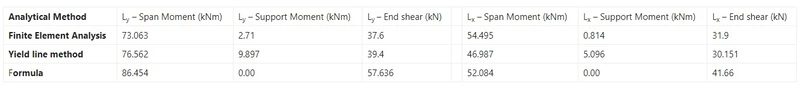
Summary Table for Two-Way Slab
One Way Slab Load Distribution on Beam:
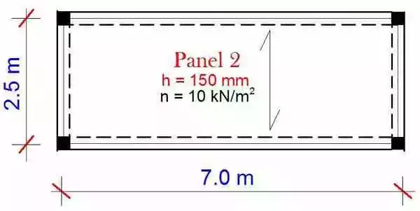
CASE 2: One-way slab of dimensions (2.5 m x 7 m) simply supported by beams on all sides and subjected to a pressure load of 10 kN/m2 k = ly/lx = 7/2.5 = 2.8
(a) Finite Element Analysis
![]()
Long span beam:
Maximum span moment = 60.689 kNm
Support moment = -6.337 kNm
End shear = 29.7 kN
Short span beam:
Maximum span moment = 12.091 kNm
Support moment = +2.81 kNm
End shear = 11.6 kN
(b) Yield line method
![]()
Long span beam:
Maximum span moment = 63.4 kNm
Support moment = -9.9 kNm
End shear = 35.9 kN
Short span beam:
Maximum span moment = 6.16 kNm
Support moment = -0.346 kNm
End shear = 7.81 kN
(c) Manual analysis using formula
Load on long span beam = nlx/2 = (10 x 2.5)/2 = 12.5 kN/m
Maximum span moment = ql2/8 = (12.5 x 72)/8 = 76.56 kNm
End shear = q1/2 = (12.5 x 7)/2 = 43.75 kN
Load on the short span beam = nlx/5 = (10 x 2.5)/5 = 5 kN/m
Maximum span moment = ql2/8 = (5 x 2.52)/8 = 3.906 kNm
End shear = ql/2 = (5 x 2.5)/2 = 6.25 kN
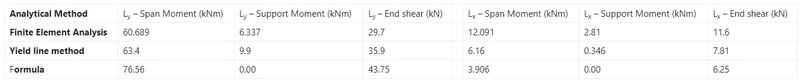
Summary Table for One-Way Slab
Discussion of results | Load Transfer from Slab to Beam
(a) Two-way slab systems
- In the long span direction, finite element analysis and yield line method gave very close results for bending moment and shear forces. Manual analysis overestimated the load transferred.
- In the short span direction, the yield line method underestimated the load transferred to the short span beams when compared with finite element analysis. The formula method gave results that are close to finite element analysis.
- Manual analysis using formula gave bending moment values that can be used for design purposes but generally overestimated the shear forces. In the long span direction, the sagging moment can be redistributed to the supports by 10% (reduce the span moments by 10% and take the value taken away as support moment).
(b) One-way slab systems
- As with two-way slabs, finite element analysis and yield line method gave very close results for bending moment and shear forces in the long span beams. Manual analysis overestimated the load transferred.
- In the short span direction, the yield line method underestimated the load transferred to the short span beams when compared with finite element analysis. Manual analysis using formula underestimated the load transferred.
- As with two-way slabs, manual analysis using formula gave bending moment values that can be used for design purposes, but overestimated the shear forces in the long span beams. The shear force and bending moment in the short-span beam were underestimated when the formula method was used.
- In the long span direction, the sagging moment can be redistributed to the supports by 10% (reduce the span moments by 10% and take the value taken away as support moment) when using formula method.
Conclusion and Recommendation:
- In a strict technical sense, there is nothing like a one-way action for a slab supported by beams on all the edges. There is always a two-way action even though it is greater in the long span.
- Formula should not be applied when assessing the shear force induced in beams supporting floor loads.
- Yield line method of load transfer from slab to beams should be used for manual design of structures, despite the more onerous computational effort.
OTHER POSTS:
-
Method Statement for Plaster Works | Cement Plastering Work Procedure
-
Method Statement for Installation of Anchor Bolts | Setting Out
-
How to Calculate Volume of Concrete in a Triangular Pile Cap – 3 Piles
-
Method Statement for Blockwork | CMU (Concrete Masonry Unit)
-
Load Calculation on Column, Beam, Wall & Slab
Conclusion:
Full article on Load Transfer from Slab to Beam | Structural Load Calculation | Load Calculation for Beam | Load Calculation of Building | Load Distribution form Slab to Beam | Structural Design Calculations | One Way Slab Load Distribution on Beam | Two Way Slab Load Distribution on Beam | Beam Load Calculation. Thank you for the full reading of this article in “The Civil Engineering” platform in English. If you find this post helpful, then help others by sharing it on social media. If any formula of BBS is missing from this article please tell me in comments.
9 Comments
Greetings my comrade, can u pls tell ur engineering friends to pls send me ,a picture or video of concrete flooring or casting of a compound pls .
1, what is the quantity of sand to a bag of cement.
2, what is the quantity of gravel needed ,to get a perfect concrete mixture.
3, what is the ideal inches or thickness for a concrete floor, that will be busy .
Thanks I hope to hear from you as soon as possible
Morris ogunorobo-ovia.
sorry i dont have video now
Hi there, i thank you so much for your simple & usefull comparison between the three methods (especially for two way slabs) but, in yield line method , what about finding the load transfer by ‘area method’ – i.e. multiplying ultimate load from slab by the area of Triangle & Trapezium and divide the whole by the length of each Triangle and Trapezium ?
Excellent knowledge of civil engineering
Thanks for the comments please visit more articles by clicking on “All Posts” tab of the Menu Bar
I love the class
Thanks for the comments please visit more articles by clicking on “All Posts” tab of the Menu Bar
Kindly sir Share the Complete Structural Designing for two Story building step by step.
I mean Steel bar Structural Designing
Thanks for the comments please visit more articles by clicking on “All Posts” tab of the Menu Bar